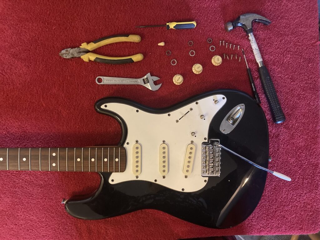
I was playing with a friend (19 June 2025) as part of a first get-together to compare notes on tastes and guitars. He was playing my Epiphone Jerry Cantrell Les Paul and I was playing the Stratocaster. At some point, there was some kind of electrical crackle which suggested a bad connection somewhere along the line.
As he hadn’t had a similar experience and we’d swapped patch cords and so on, I concluded that it was most likely caused by some minor defect in my recent replacement of the output jack (I had replaced the original some time back with a fairly cheap option I found on Amazon, where the cord had a tendency to drop out, so I’d bought a proper Switchcraft unit from Long and McQuade in Waterloo, Ontario), but then it again, figured it might well be something else. The guitar was some 35 years old by this point, so it was certainly conceivable. So I figured it might be worthwhile to look at some kind of upgrade rather than just tinker with the jack yet again and/or horse around looking for other issues.
I read a variety of reviews and considered options, and eventually settled on an ObsidianWire Custom 250K Blender for Strat replacement (CAD 149.99 plus tax and 8.95 shipping, through Amazon rather than the Canadian distributor, Solo Music Gear, for ease of return in the event of any issue). The rationale was a combination of
- price
- ease of installation (no soldering required, just plug-’n-play!)
- additional choice in tone, since pick-ups can be blended at a chosen ratio rather than as set by Fender
- New Zealand company, rather than US (though components are US, mind you).
It wasn’t particularly difficult, and the results are highly satisfactory. A few adjustments were needed, and there was a minor hiccup at the end, but given the age and model, this was to be expected. The step-by-step process follows.
Disassembly
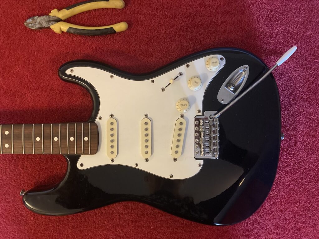
Remove the strings
The first thing to do was to remove the strings in order to gain access to everything else. That was no great loss, as they’d been on the guitar since September 2024 (so about 10 months) and they had it coming. This was easily done using a pair of pliers.
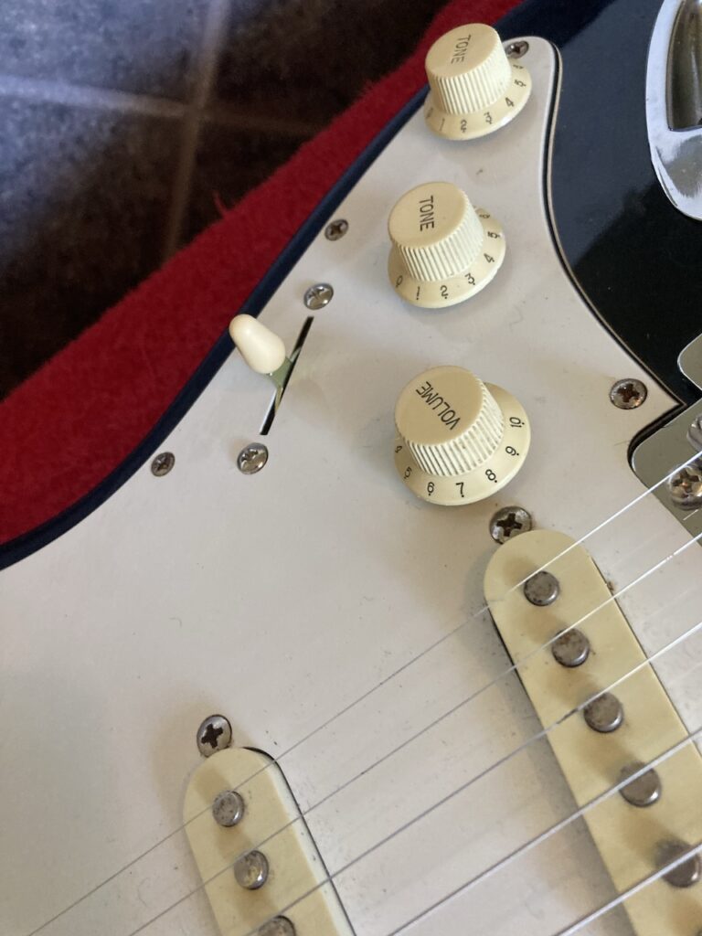
Remove the knobs
Next, I had to pull off the volume and tone knobs as well as the selector switch knob. I used the claw of a hammer, and a screwdriver to pry off the volume and tone knobs. I made sure to place an underlay on the pick guard to make sure it didn’t get scratched in the process, and do it slowly and carefully so as not to break anything.
The best thing would have been to go to my shed to get the claw-end screwdriver (whatever those are called), but you know how it is: you can spend 30 seconds and go and get the right tool, or you can spend an hour trying to get it done with the wrong tool you have handy, and the wrong tool wins every time LOL!
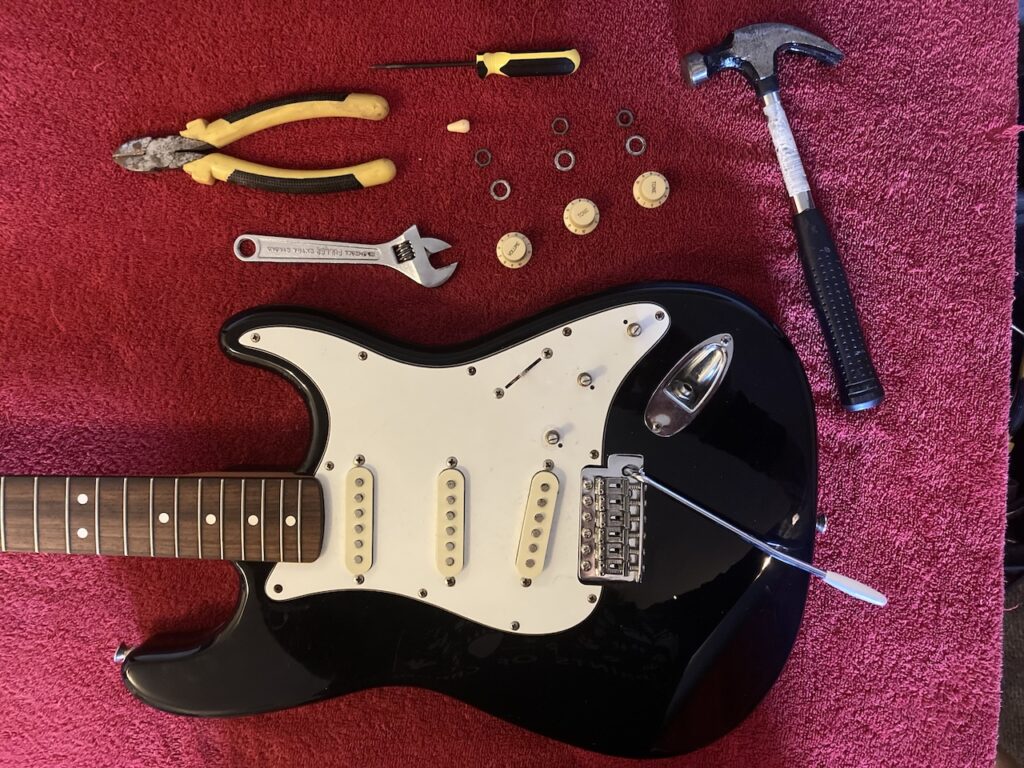
Remove retaining nuts
The potentiometers are held in place with nuts, so those have to be removed in order to allow the potentiometers to be disconnected from the pick-guard and removed.
Once again, the better thing would have been to use a socket, open-, or closed-end wrench to avoid damaging the nuts, but that would have involved a trip to the neighbour’s, where my wrench set was currently residing courtesy of some maintenance on my Kubota BX25 tractor which was being done in his much larger shed, with his assistance. But the adjustable wrench worked just fine.
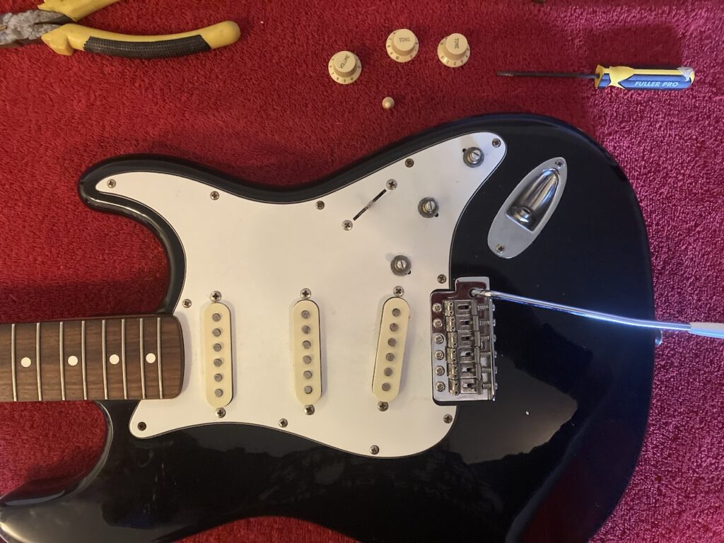
Remove pick-guard screws
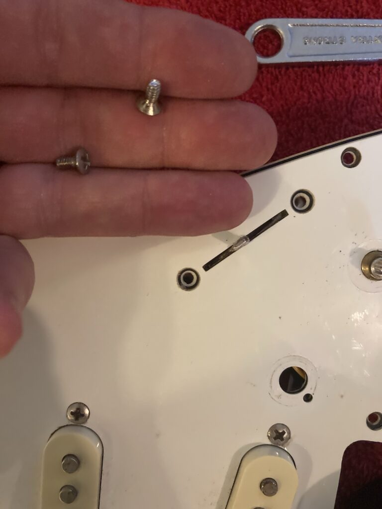
After that, I removed the pick-guard screws using a small Phillips screwdriver. No big deal.
As you can see, they are a bit rusty, courtesy of the guitar having sat in my shed for a summer, so I should replace them at some point, but that’s not terribly urgent….
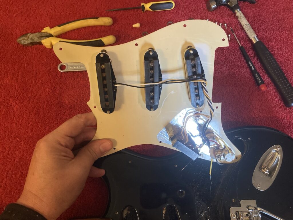
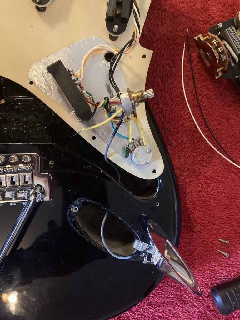
Remove the pick-guard
At this point, the pick-guard just lifts off. Still, one wants to be careful, since there are wires from the components under the pick-guard to the output jack and the ground connection at the back of the guitar.
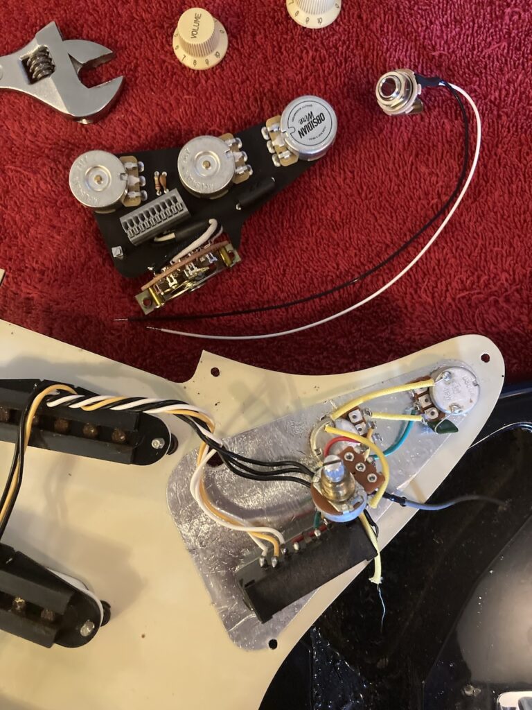
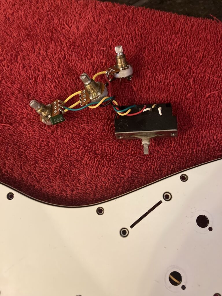
Comparison of old and new parts
A good time to take stock: see where we are, consider where we are going, before doing anything we’re going to regret! As you can see, whereas the old potentiometers are individually mounted, the new set are fixed onto a plate. That makes for solidity… but potentially an issue if and when things don’t match perfectly.
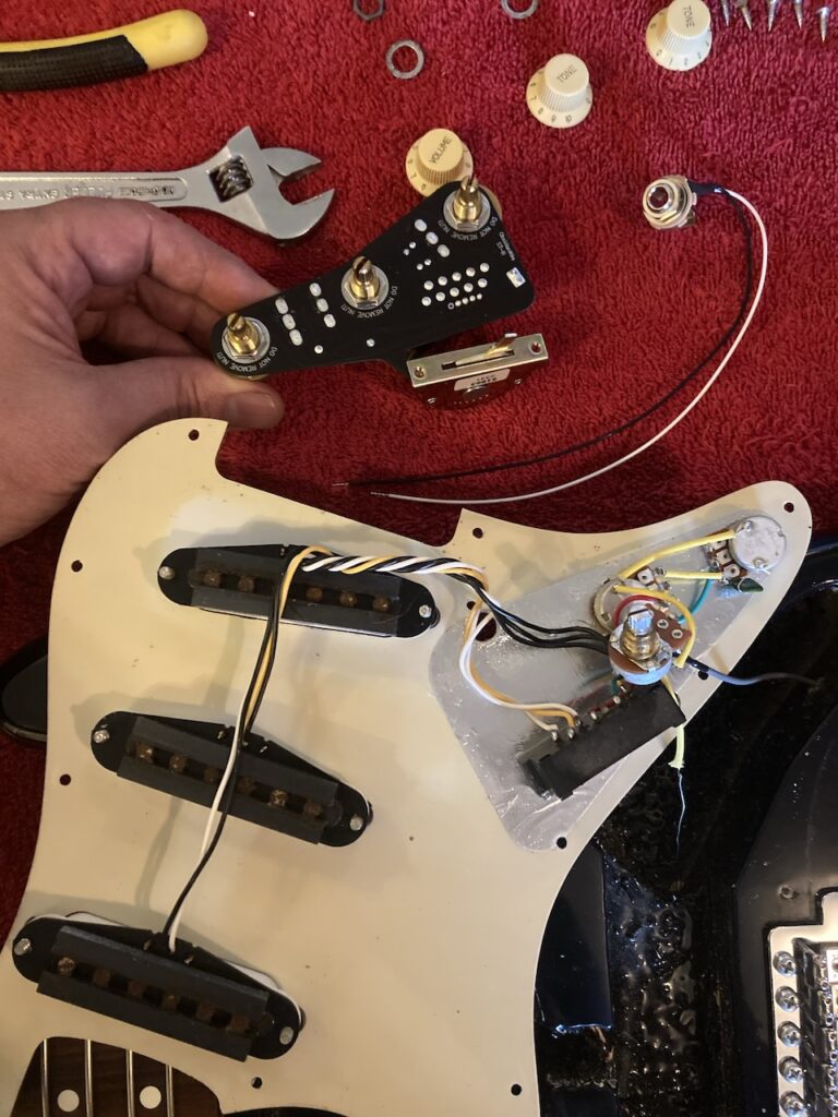
Replace the output jack
The output jack (often mistakenly called ‘input jack’ because the patch cord from the guitar is plugged ‘in’ there) is separate from everything else, physically, but needs to be connected to the central connector, so it made sense to do it next.
It’s a pretty simple procedure:
- remove the screws holding the output jack holder in place
- cut the single wire from the jack at the place where it is soldered to the old potentiometer
- slide the jack assembly out
- remove the nut holding the jack in place
- replace it with the new jack
- thread the new nut onto the jack
- thread the two (!) wires from the new jack through the hole where the old wire was, and
- screw the jack assembly back into place.
That’s it for now; we’ll come back to the output jack wiring later.
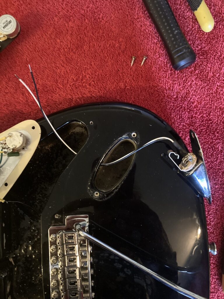
Remove the ground wire
There is a ground wire from the claw at the back of the guitar body which runs through the body into the central cavity and is connected to the old components. This needs to be cut, near to the old parts, in order to free up the pick-guard and components for further work. Make sure to keep the sleeve, as it insulates the wire against potential contact with other things down the road.
Before going any further… Take stock!
We’ve probably all disassembled something with great eagerness, repaired whatever it was, and then … realized we no longer remember where all the parts came from. I’ve done that more than once.
As you can see from this page, I’ve documented everything I did with photos along the way. It’s easy to keep them in sequence since the camera numbers them sequentially, which is a great help (and the time stamp serves the same purpose, which is good, because…); I rename the images as well with meaningful names (i.e., not using cryptic short mnemonics, as I was fond of doing as a junior programmer back in the day) so that I’ll remember the purpose of the image. Taking notes would not be a bad idea either.
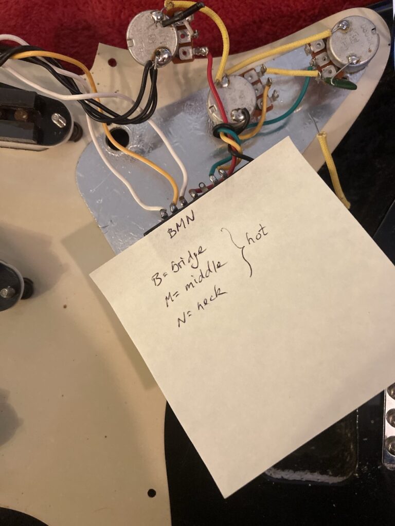
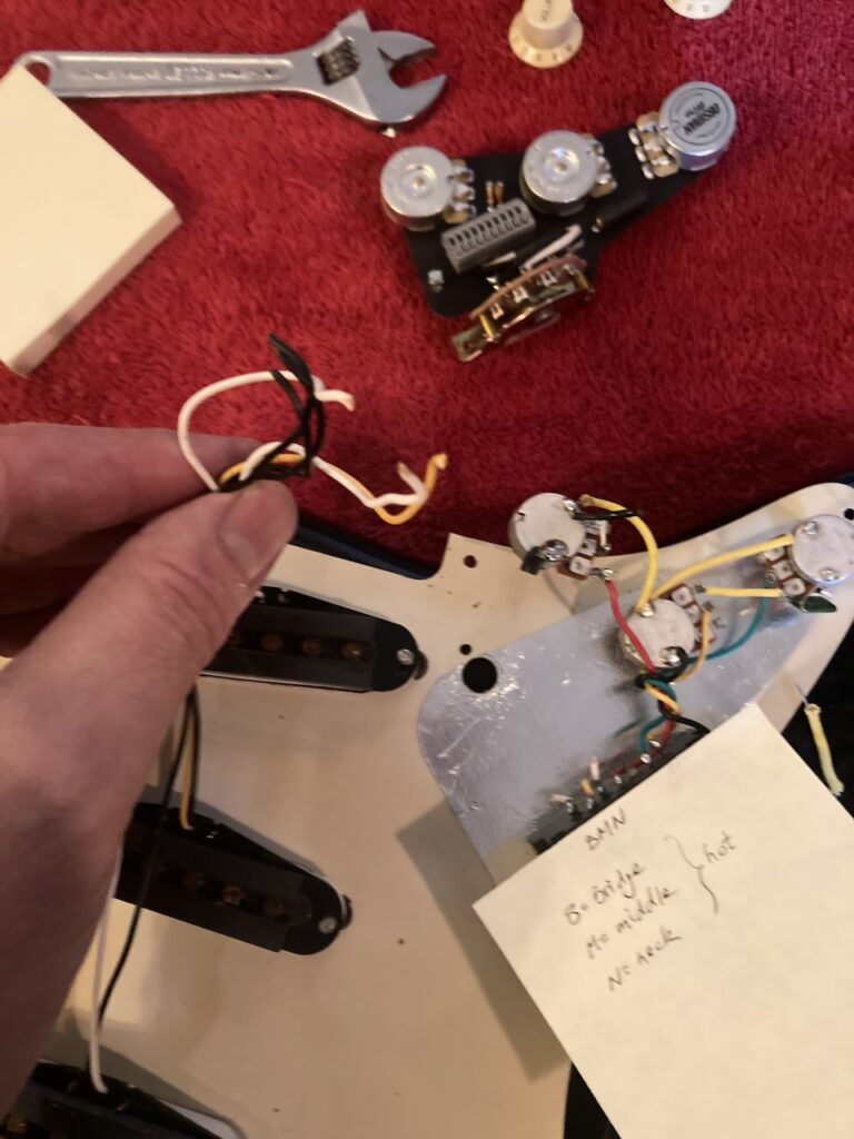
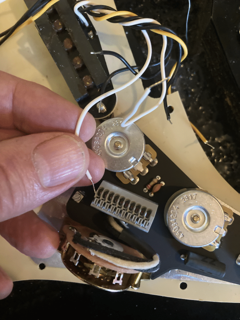
That said, photos don’t always tell the whole story. For example, in the immediately preceding photo, you will see in the top left three wires (two white, one yellow) which are the hot wires from the pick-ups. Well, there are three pick-ups (big surprise there) and while it is no problem figuring out from the photo where the yellow wire was before being disconnected, the same is not true for the other two! Does we care?
Well, if the goal is to wire in the new part and throw away the old ones, it may not; but say someday we change our minds or buy a part like the original, it might be nice to know where the original wires were. In any case, I find it’s generally better to over-document and not need information than it is to take the quick route and discover that we no longer have access to information we need after all. So, I carefully traced the wires back to their source, attached a diagram, and took a photo for posterity.
By the way—I checked and rechecked a few times, just to be on the safe side.
Disconnect the pick-ups
Now it’s safe to cut the hot wires from the pick-ups.
Remove the selector switch
The selector switch is held in place by two screws through the face of the pick-up guard. So, time to turn over the pick-guard again and remove those.
At this point, all the old parts come free and we can start working on the new assembly!
Reassembly
Strictly speaking, this should read ‘Reassembly, with the exception of the output jack’, since the new one has already been installed. But that doesn’t look so nice! 😊
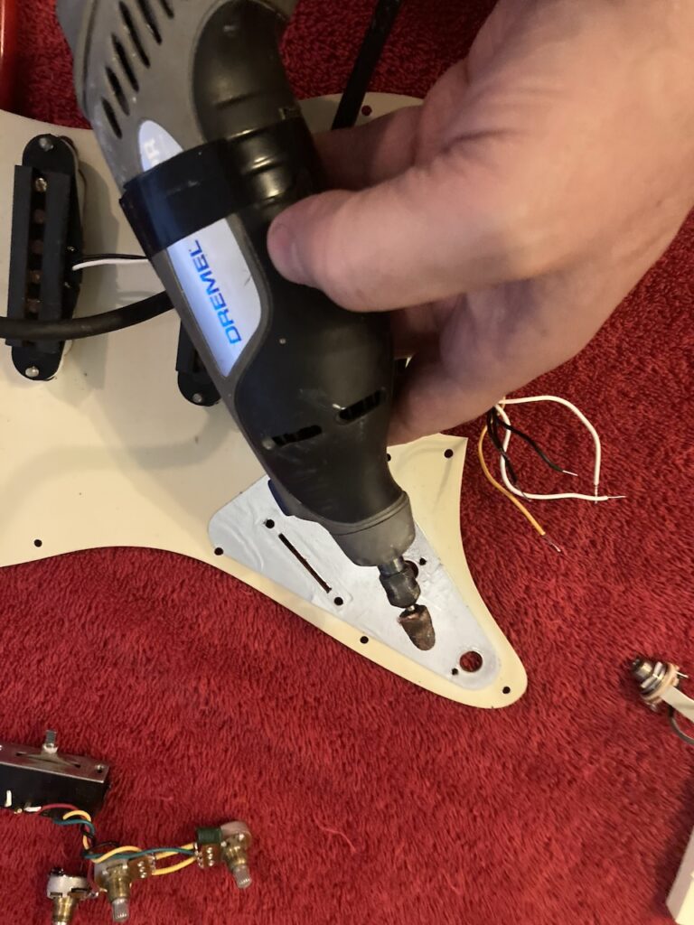
A first attempt at matching the new assembly to the pick-guard revealed a few surprises (well, to be honest, I wasn’t surprised, I’d anticipated these). First of all, the holes through which the potentiometer shafts were to be fed were too small, just slightly, thanks to the difference in parts used in this model versus the other, presumably more common ones. So, they had to be enlarged.
This was not a big deal, thanks to my Dremel tool and ideally-sized parabolic sanding tip. The key here is ‘slowly, but surely’—we can remove more plastic, but we can’t put it back. So it was enlarge, test; enlarge, test; … until the holes were just large enough.
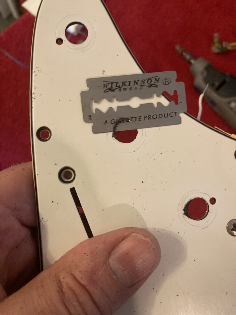
The second issue was that the placement of the potentiometers was ever so slightly different from the original set, meaning that I had to then enlarge the holes just a tad more to compensate. Fortunately, this was on the order of a millimetre or so from end to end. That means that any excess hole perimeter would be easily covered up by the knobs. Of course, ‘dremelling’ the pick-guard resulted in burring, which anyone with any professional pride would want to remove. Since I use a standard, old-fashioned razor (my maternal grandfather’s, as it happens), I had plenty of used blades which I keep for just such tasks.
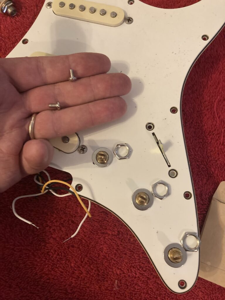
Mount the new assembly
Mounting the new assembly was straightforward:
- fit the potentiometers through their respective slightly enlarged holes
- slide the switch handle through the slot
- fasten the potentiometers with the supplied washers and nuts (tightly, but not excessively), and
- fasten the switch in place with the shiny new mounting screws.
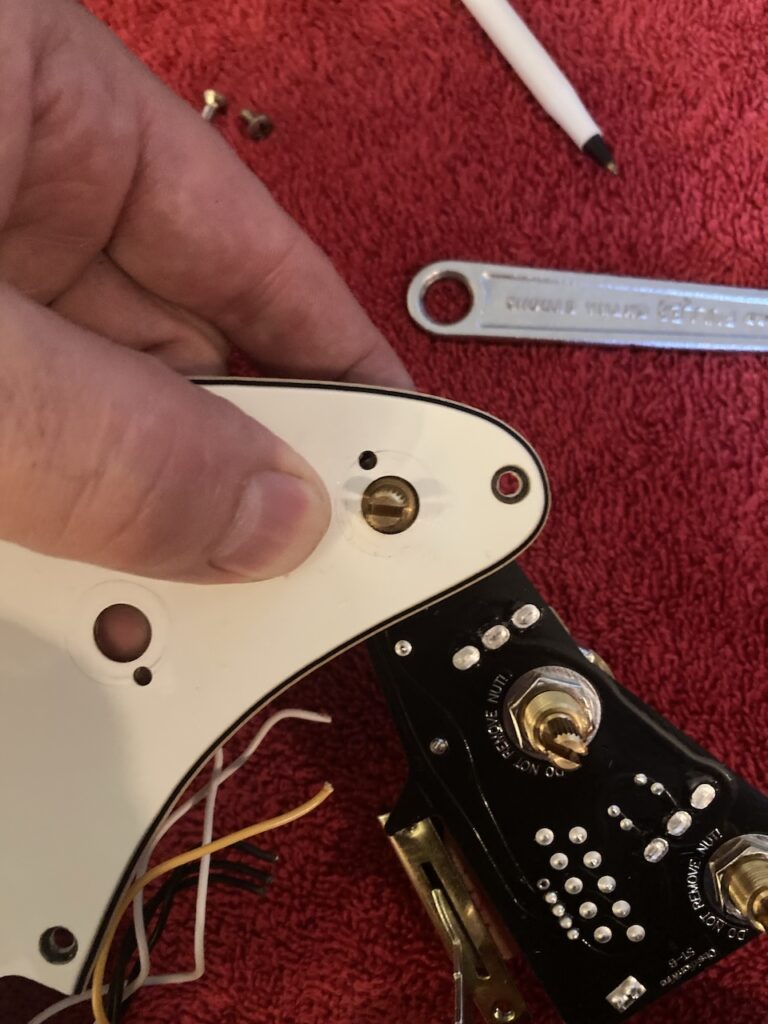
I noticed that the small holes by the side of the potentiometer shaft holes were mostly covered up by the new washers. Ideally, I should maybe have enlarged those (I assume they are used for a quick burst of contact cleaner into the potentiometers from time to time, so as to avoid removing the pick-guard plate), but I decided to leave that to another time as I really wanted to get the job done.
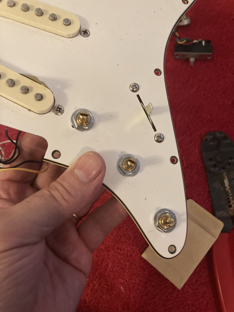
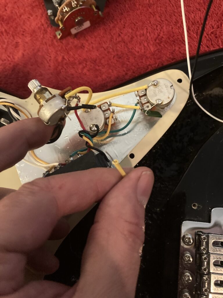
Connect the wiring
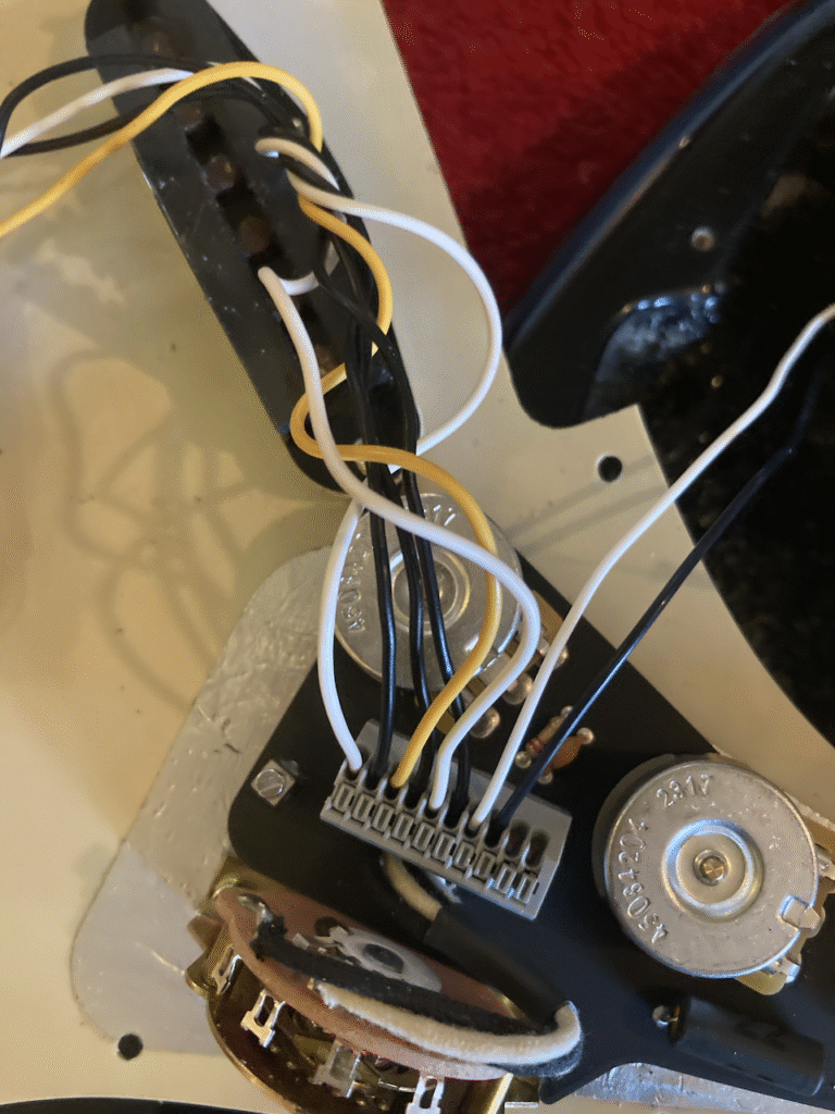
Wiring the thing up was really quite straightforward. The handy diagram show exactly what goes where, including the extra ground wire from the output jack. A main difference between this assembly and the original is that ground wires are all connected individually here rather than ganged up, which will likely be a boon if and when a given component needs replacing in future.
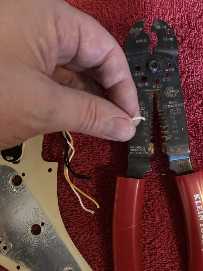
Since the original wires were cut, of course the ends must be stripped, first, to the length specified by the instructions.
Connecting a wire is simplicity itself: press the corresponding button to open the hole, insert the wire, release, much as is done with speaker wires at the back of many modern stereo systems (in North America, anyway—I prefer DIN plugs, myself, but for some strange reason, I’m not in charge!).
In each case (3 pick-ups and output jack) the order is, starting from the left, hot wire, then ground wire. The ground wires are the black ones in the images.

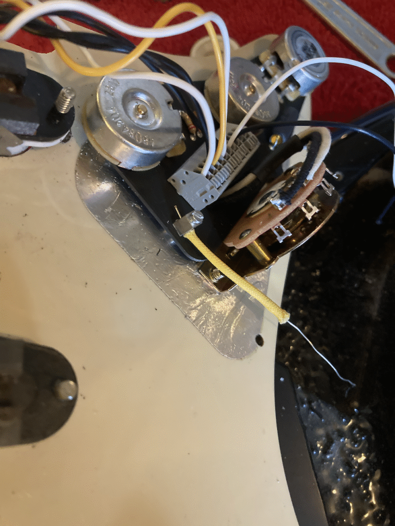
Connect the body ground wire
Only one wire left to go—the one from the claw at the back of the guitar through the body. There’s a special place to hook that up by means of a hole and screw. Once fastened in, the sleeve should be slid up to it to keep the wire from touching anything else.
Replace the pick-guard
Everything has now been mounted and wired, so it’s time to put the pick-guard back into place.
At this point, I noticed that the tone potentiomenter (now a ‘blender’) was very tight against the body cavity. It did fit in with a bit of persuasion, but at this point it really would have depended on the degree of tightness. I decided it was not severe, otherwise I’d have had to enlarge the body cavity just a little bit at that point.
Mount the knobs
This was the last task before restringing. I didn’t anticipate any further issues, which just shows a lack of imagination on my part….
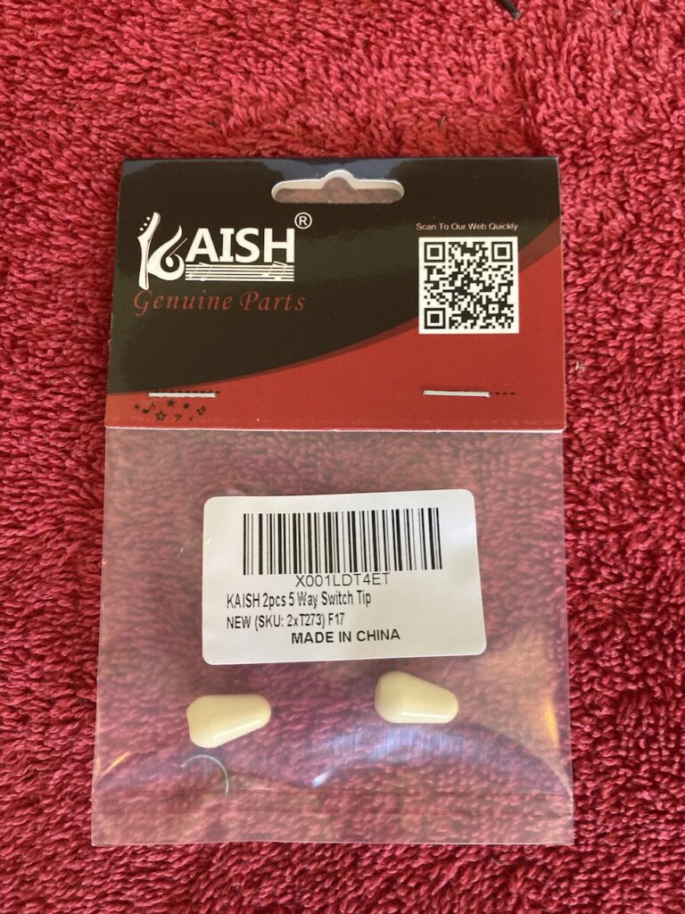
The volume and tone control knobs were not a problem. However, the selector switch knob didn’t fit! It turns out that my original selector switch tab was about 1mm less wide, and somewhat less thick, than the replacement. Argh! I briefly considered using the Dremel to shave the metal to fit… and then decided that I ran the risk of damaging it, or something else in the process. So I opted for the alternative… buying a new knob which would fit. Fortunately, the clever (or greedy, as you prefer) vendors offer ‘aged white’ for those of us who want to make it look as though the parts are original….
There went another CAD 9.99 plus tax. But, hey, it’s an upgrade, right? More solid than before? And now I have a spare knob, in case I lose it. (That’s a nicer way to look at it than to say, ‘So that’s how they justify the ridiculous price for a plastic knob’. Then again, even at two in a package, 9.99???)
And th-th-th-that’s it, folks … (or is it?)
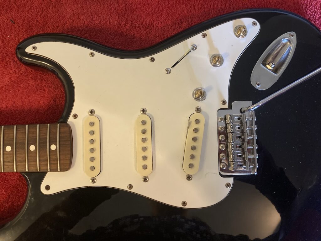
And that was that. I worried a little about whether I’d in fact done everythign properly, whether the wires were solidly connected, and so on, but all was fine. The guitar worked like a charm once I mounted new strings and plugged it in. I was so proud of my work, I just had to show it off.
And my friend said, …
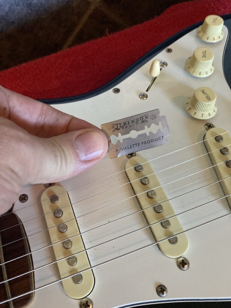
What’s the purpose of that razor blade, there?
Eh? Say what?
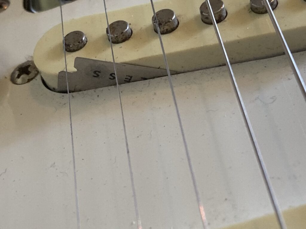
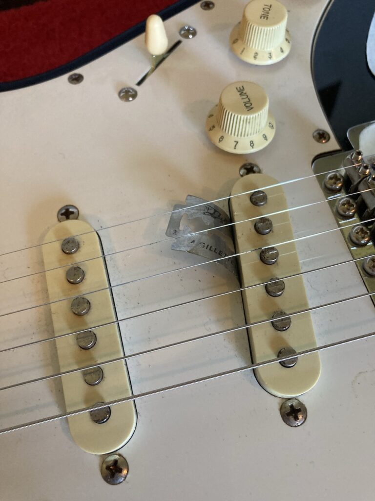
I had in fact misplaced the razor blade at one point in cleaning off burrs (I frequently misplace tools within a very small distance from me) and couldn’t find it for the life of me. That was because the magnet in one of the pick-ups had snatched it up, somehow, and it lay alongside the pick-up, partway in the body cavity, partway outside. If you scroll up to an earlier image, you can see it if you look closely.
Ah, la barbe, alors! Do I have to ruin these brand new strings and take the thing apart? (Small consolation: the brand new strings came ‘pre-rusted’ in places; how thoughtful of Fender!) So I tried to pull it out with the pair of pliers you may have noticed above. And it worked!
The final product
All’s well that ends well. The minor mishap was no big deal, and I now have a nicely playing Stratocaster with improved tone options. All told, I spent maybe a few hours on this, and partly only because I was being particularly cautious about it all.